For some, Entity Relationship Diagrams (ERDs) are old friends that you still visit once in a while and have some fun with. For others…not so much. Let’s try to help the latter get up to speed on ERDs.
An Entity Relationship Diagram (ERD) is a visual representation of different data using conventions that describe how these data relate to each other. While able to describe just about any system, ERDs are most often associated with the complex databases used in software engineering and IT networks. In particular, ERDs are frequently used during the design stage of a development process to identify different system elements and their relationships to each other. As you might imagine, this can be particularly helpful when modernizing a database.
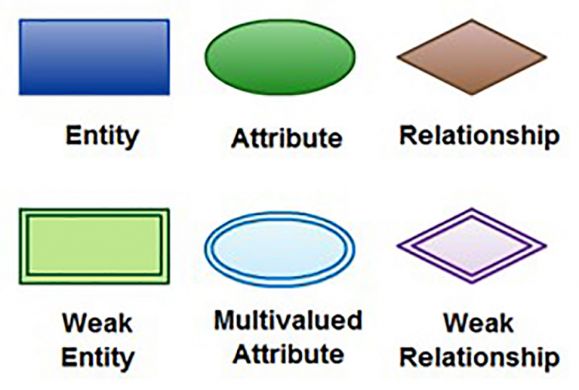
There are three basic elements in an ERD: entity, attribute, and relationship. There are more elements based on these three main elements. They are weak entity, multivalued attribute, weak relationship, derived attribute, and recursive relationship. All but the last two of these elements are shown in Figure 1. I’ll talk about derived attributes and recursive relationships later.
Figure 1: ERD basic elements
What’s an Entity, Anyway?
Let’s take a quick tour of these elements, starting with the entity. An entity can be a person, place, event, or object that is relevant to a given system. For example, in an inventory system, entities might include clients, suppliers, warehouses, items, and fees. Entities are represented in ERDs by rectangles and named using singular nouns. A weak entity is a special type of entity that depends on the existence of another entity. In more technical terms, it can be defined as an entity that cannot be identified by its own attributes. It uses a foreign key combined with its attributes to form the primary key. For example, an order item is a good example of this type of entity. It is meaningless without an order, so it depends on the existence of order.
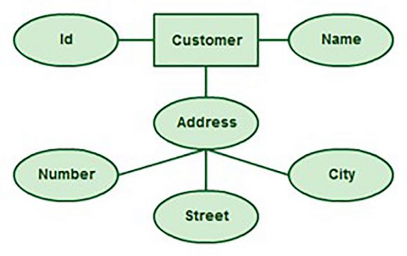
Typically, entities have attributes, the same way a record has fields. An attribute is a property, trait, or characteristic of an entity, relationship, or another attribute. For example, an inventory item entity can have the attribute “inventory item name." An entity can have as many attributes as necessary, and attributes can have their own specific attributes. For example, the customer address attribute can have the attributes number, street, city, and state. These are called composite attributes.
Some top-level Entity Relationship Diagrams do not show attributes, for the sake of simplicity. In those that do, however, attributes are represented by ovals, as shown in Figure 2.
Figure 2: An example of ERD attributes representation
You must distinguish between composite attributes, like the address attribute in Figure 2, and multivalue attributes. A multivalue attribute can have more than one value at the same time. Because it’s not very practical in database systems, it’s usually implemented in the physical model using primary and secondary tables, like the Client Master and Client Address tables from the 1NF example from the previous article.
Let’s use normalization to explain yet another variation of the attribute: the derived attribute. This is simply an attribute based on another attribute. A good example of this is the item weight in kilograms from the 3NF example. Because you can calculate the weight in kilograms from the weight in pounds, you can say that the first one derives from the second. If you were to represent that table in an ERD, you would use the derived attribute notation, an ellipse with a dashed outline. This is rarely found in ERDs.
Relationships—Some Are Simple, Some Are Complex
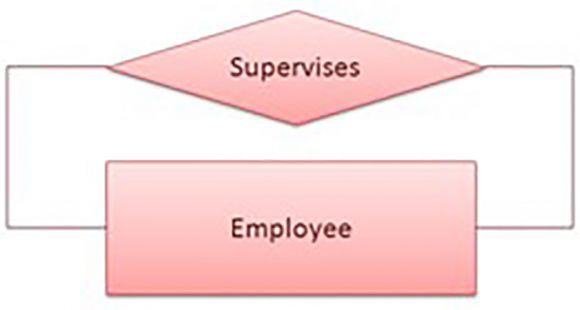
Now that we’ve covered the entity element of the diagram name, let’s move on to the relationship, starting with a generic definition of what a relationship is: a relationship describes how entities interact. For example, the client entity may be related to the order entity by the relationship “places” or “makes.” Relationships are represented by diamonds and are labeled using verbs. However, an entity can also have a relationship with itself. For instance, an employee entity could contain an attribute called “supervisor” and have a relationship with itself that defines the hierarchical structure. This is a recursive relationship, as shown in Figure 3.
Figure 3: An example of a recursive relationship.
Here, the “Supervises” recursive relationship indicates that an employee is supervised by another employee. However, this is not enough to fully represent how the relationship works, because it only describes that a relationship exists between two entities. To fully represent the relationship, you need to define its cardinality. In other words, you need to explicitly show how the information from one entity in a relationship matches the information from the other entity.
For instance, in the Client Master/Client Address scenario, a Client Master record can have one or more matching records (records with the same client ID) in the Client Address table. This is a “one-to-many” relationship. On the other hand, each Client Address record can only match one record in the Client Master table. This represents a “one-to-one” relationship. A number of notations are used to present cardinality in ERDs. Chen, UML, Crow’s Foot, and Bachman are some of the popular notations.
Tips for Creating Good ERDs
Because Entity Relationship Diagrams are simple enough to understand, just about anyone can create them. However, two different ERDs describing the same system may still be radically different in terms of their simplicity, completeness, and efficiency at communicating the system. In other words, there are good ERDs, and there are really bad ones. Here are some tips that will help you build effective ERDs:
- Identify all the relevant entities in a given system and determine the relationships among these entities.
- An entity should appear only once in a diagram.
- Provide a precise and appropriate name for each entity, attribute, and relationship in the diagram. Terms that are simple and familiar always beat vague, technical-sounding words. In naming entities, remember to use singular nouns. However, adjectives may be used to distinguish entities belonging to the same class (part-time employee versus full-time employee, for example).
- Attribute names must be meaningful, unique, system-independent, and easily understandable.
- Remove vague, redundant, or unnecessary relationships between entities.
- Never connect a relationship to another relationship.
- Make effective use of colors. You can use colors to classify similar entities or to highlight key areas in your diagrams.
You can draw Entity Relationship Diagrams manually, especially when you are just informally showing simple systems to your peers. However, for more complex systems and for external audiences, you need diagramming software to craft visually engaging and precise ERDs. Some of the tools presented in the next article will help with that. Until then, please share your experience, questions, and thoughts using the comments section below. You might help a fellow reader or even find that piece of information you’ve been looking for!


LATEST COMMENTS
MC Press Online