Let's suppose you're an AS/400 manager at a middle market company that has just bought out a competitor that also uses OS/400.
One day, the president E-mails you and writes, "...We really need access to the new company's AS/400. Nothing fancy. Just let us dig into their books. Oh, and we need it to prepare for next week's shareholder's meeting."
Being an intelligent MIS manager, you E-mail back the answer any intelligent MIS manager gives in this situation: "No problem."
Fortunately, there is a way out. You can use an old, reliable dial-up connection that IBM gave you free. It configures easily, uses existing telephone lines and modems, and isn't a major hassle to run. It's a dial-up SDLC connection, and it's so easy to set up that you can do it while watching a presidential address or the Super Bowl...or in your sleep, whichever comes first.
Interested? Well, if you're the poor MIS manager in this article, you probably don't have much time, so I'll get started.
In this situation, there is no time for setting up a SNADS configuration. You must quickly establish a telecommunications link between two AS/400s for data viewing. I'll focus on the practical aspects of using your existing telecommunications equipment, configuring the AS/400 communications lines on both machines, connecting the two machines through SDLC, and providing display station passthrough (DSPT) access.
Later, when this basic configuration is set up, you can focus on adding remote system printing, Client Access support, and file and message forwarding functions to the connection. You add some of these functions by setting up a SNADS configuration between the two machines that will run over your SDLC line. While not difficult to configure, a SNADS configuration is harder to understand and troubleshoot than this SDLC connection.
You probably have everything you need to set up a basic SDLC connection. For this example, you need an IBM-approved SDLC-capable modem and a phone line that supports incoming and outgoing calls.
For a quick configuration between two AS/400s, you can use the Electronic Customer Support (ECS) modem installed on your machine to download PTFs. In many cases, this modem is not used very often and is the perfect candidate for an SDLC connection. By using the ECS modem, you save yourself the time and expense of ordering additional SDLC modems, such as the IBM 7855, and installing them on your AS/400 and the AS/400 you're connecting to.
There is one pitfall in this approach, and it can hit you hard unexpectedly. Using the ECS modem for communications with another office will necessarily limit your ability to use the modem for ECS. Normally, this is not a big problem as most people use ECS infrequently. Its usage can be bumped over to off hours when you won't need the inter-AS/400 connection. The situation can be difficult, however, when your entire shop is waiting for something to come in over ECS and your internal users won't let you sever the connection. I recommend using the supplied ECS modems to set up the connection and then, once everything is stable, adding an additional modem, communications adapter, and phone line to both locations to be used just for the inter-AS/400 connection.
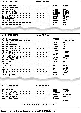
1 shows you most of the information you'll need from both machines to create an SDLC connection. (In the example in this article, I'm connecting system MCPGMR to system MC.) You can get this information by running the Display Network Attributes (DSPNETA) command and selecting the *PRINT option. You must run this command on each machine to get both sets of parameters.
Figure 1 shows you most of the information you'll need from both machines to create an SDLC connection. (In the example in this article, I'm connecting system MCPGMR to system MC.) You can get this information by running the Display Network Attributes (DSPNETA) command and selecting the *PRINT option. You must run this command on each machine to get both sets of parameters.
The only other pieces of information you'll need are the phone numbers of the ECS modem lines on each machine and the AS/400 resource names the ECS modems are attached to. The resource name is simply the AS/400 hardware address of the communication card your ECS modem is hooked up to. For most machines, the ECS port number is LIN011. To find this address, run the Display Line Description (DSPLIND) command on your ECS line (often called QESLINE); the address is the value in the Resource names (RSRCNAME) parameter.
Armed with this information, you can do the configuration.
As I mentioned, IBM gives you a basic SDLC configuration free with OS/400. There isn't a lot of work involved in setting up terminal access between two AS/400s in different locations. Most of the work is done through the Communications Configuration Tasks menu. You access this menu by typing in the following command:
GO CMNCFG
CMNCFG is a simple but powerful menu for creating communication lines to contact remote systems using SDLC, token-ring, or Ethernet lines. This menu can create line and controller configurations over a network, through dedicated (nonswitched) phone lines, or through dial-up lines. You can also use it to create configurations for accessing remote workstation controllers.
You must use the CMNCFG menu options on both AS/400s, but it doesn't matter which AS/400 you configure first. As you'll see, the configuration for the second AS/400 is dependent on the values you enter for the first system.
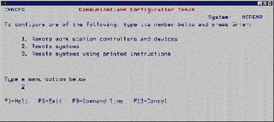
2 shows the Communications Configuration Tasks screen, the first of a series of screens that guide you through the configuration process. On the first machine you configure, select option 2, Remote systems, from the menu.
Figure 2 shows the Communications Configuration Tasks screen, the first of a series of screens that guide you through the configuration process. On the first machine you configure, select option 2, Remote systems, from the menu.
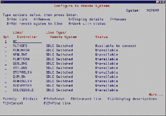
Selecting option 2 brings up the Configure to Remote Systems screen shown in 3. On the line description display, type in 1 and the name of the SDLC line you want to create. In the example, to create an SDLC line that allows the local machine to call the remote machine, you type 1 and specify MC as the name of the line you want to create.
Selecting option 2 brings up the Configure to Remote Systems screen shown in Figure 3. On the line description display, type in 1 and the name of the SDLC line you want to create. In the example, to create an SDLC line that allows the local machine to call the remote machine, you type 1 and specify MC as the name of the line you want to create.
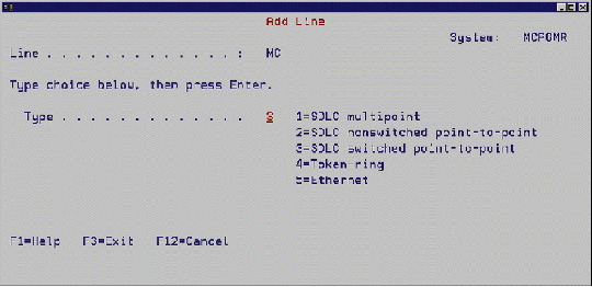
The menu will then prompt you for specific information about the line you want to create (see 4). It will ask you if you want to create a multipoint, a nonswitched point-to-point, or a switched point-to-point SDLC line. Since you are running the connection on nondedicated switched lines, choose option 3, SDLC switched point-to-point, and press Enter.
The menu will then prompt you for specific information about the line you want to create (see Figure 4). It will ask you if you want to create a multipoint, a nonswitched point-to-point, or a switched point-to-point SDLC line. Since you are running the connection on nondedicated switched lines, choose option 3, SDLC switched point-to-point, and press Enter.
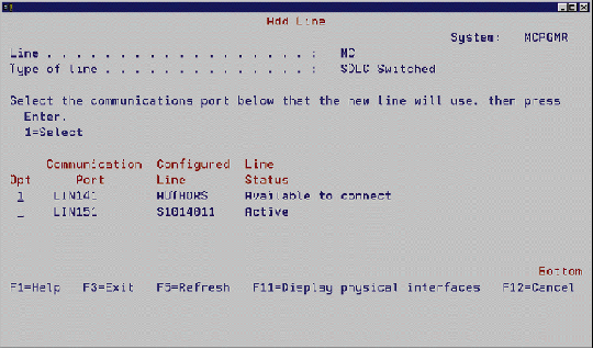
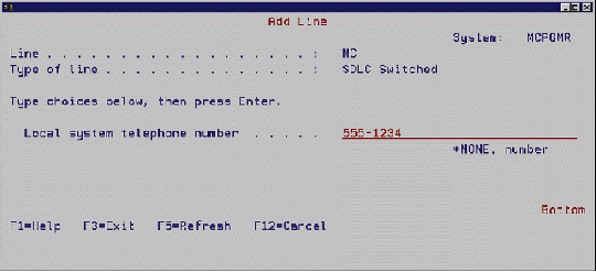
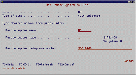
The next screen, as shown in 5, allows you to specify the AS/400 communications port you want to use. Another series of prompts, shown in6 and 7, asks you for the following four parameters. Here, it's fairly easy to get confused and enter a wrong value, so be careful.
The next screen, as shown in Figure 5, allows you to specify the AS/400 communications port you want to use. Another series of prompts, shown in Figures 6 and 7, asks you for the following four parameters. Here, it's fairly easy to get confused and enter a wrong value, so be careful.
Local system telephone number is the phone number of the system you are dialing from. This is not important for dialing out to the remote system, but it does become important when it's time to configure the remote system. What you enter here will be printed in the instructions for configuring the remote system.
Remote system name is the default local location name from the DSPNETA list you printed for the system you are connecting to.
Remote system type specifies whether the system you are calling is an AS/400 or a S/36.
Remote system telephone number is the phone number your AS/400 dials when it uses the SDLC line to call the remote system.
After entering these parameters, press Enter. A new SDLC communications line is created, and the display tells you to look for printed instructions on configuring the remote system for SDLC use. These printed instructions are so clear and easy to use that you could fax them to the remote location and let the local staff there configure that SDLC line; however, I'll proceed as though you're configuring the remote system.
At the remote AS/400, use the printed configuration instructions and type in the GO CMNCFG command again. This time, though, select option 3, Remote systems using printed instructions (see 2). Then follow the printed instructions, and a second line will be created on the remote system that can be used in SDLC communications.
At the remote AS/400, use the printed configuration instructions and type in the GO CMNCFG command again. This time, though, select option 3, Remote systems using printed instructions (see Figure 2). Then follow the printed instructions, and a second line will be created on the remote system that can be used in SDLC communications.
When you complete the instructions for the remote system, you will have set up a connection between the two systems, complete with communications lines and all the necessary controller configurations. To connect to the remote system, start a passthrough session using the local location name of the system you want to connect to. For example, to start a session on the remote system from the local system, you would enter the following command:
STRPASTHR MC
If the machines are not already connected by an SDLC line, the local AS/400 dials the remote AS/400 and initiates a session. A passthrough session running over the SDLC line performs the connection. Once the session is active, any user on either AS/400 can start another session by using the active SDLC line to initiate a different passthrough session on the other machine.
To disconnect from the remote machine, the user can end passthrough by issuing the following command:
ENDPASTHR
This command disconnects the user's individual session from the remote machine. If other people are using passthrough between the two machines, however, the SDLC connection will remain active. When the last person using the connection signs off, the dial-up SDLC connection is severed. It is reestablished the next time someone requests a passthrough session on either machine.
Once you have a simple SDLC connection set up, your users will begin looking for more services from the connected AS/400. Remember that the configuration outlined here is just for terminal emulation between two AS/400s. It provides nothing else.
Getting other inter-AS/400 features-such as remote printer support, file exchange, and message exchange-may require a SNADS configuration between the two systems. A SNADS configuration is more complicated than the simple configuration outlined here, and there is no centralized menu for setting one up. For more information on how to configure SNADS, see "Getting Started with SNADS," MC, May 1994.
When all you need is basic terminal support between two AS/400s, it's hard to beat an SDLC configuration for ease of setup and ease of use. So, the next time your president calls up with a seemingly impossible demand to hook up two AS/400s quickly over a dial-up line, just say, "No problem."
Editor's Note: This article was originally written and tested using two AS/400s at V3R0M5, and everything worked as described. When we tested the configuration procedures here at MC, we used V3R1. During our testing, we encountered some problems getting the modem to dial when it was supposed to (at the time you run the STRPASTHR command). We contacted IBM, and they confirmed that there are problems with dial-up SDLC connections in V3R1. By the time you read this, one or more PTFs should be available. If you're at V3R1, be sure your systems are up-to-date with the latest cumulative PTF tape.
Joe Hertvik is a freelance writer and a system administrator for a manufacturing company outside of Chicago.
Your Dial-up SDLC Connection
Figure 1: Sample Display Network Attributes (DSPNETA) Report
Your Dial-up SDLC Connection
Figure 2: The Communications Configuration Tasks Screen
Your Dial-up SDLC Connection
Figure 3: The Configure to Remote Systems Screen
Your Dial-up SDLC Connection
Figure 4: Selecting a Line Type
Your Dial-up SDLC Connection
Figure 5: Selecting a Communications Port
Your Dial-up SDLC Connection
Figure 6: Entering the Local System Telephone Number
Your Dial-up SDLC Connection
Figure 7: Entering the Remote System Information


LATEST COMMENTS
MC Press Online