But Java as a language brings very little to the table without first looking at OO design. The maximum return on an investment in Java and OO can be achieved at the enterprise level. While it is unrealistic to think that many shops will embark on a project to rewrite all their legacy applications and replace them with Java-based OO systems, it may be worth your while to spend some time and effort developing an OO design strategy and beginning to explore the gradual migration to OO-based systems.
To realize the benefits of OO design and Java, you need a comprehensive enterprise model and architecture that identifies your enterprise's business objects and the relationships that exist between these objects. You must then explore and understand the methods that exist within these objects to support your business operations. The process is a top-down methodology that uses functional decomposition to get to the details of system design. Once a business model is created, you will find that you can work on various parts and components of the model.
We have all heard a great deal about Model/View/Controller(MVC or Model-2). This design paradigm is a methodology to separate presentation and workflow (View is presentation; Controller is workflow). What has not been discussed in much detail is the "model" component of MVC. It is the model that is the very heart of your system. It is the collection of and the relationships between the key business objects and the business rules governing those objects that exist in your enterprise.
A model object can be a simple business object such as "Employee" or an extremely complex object such as an insurance company's "Policy." In a large multi-line insurance company that handles many different types of insurance, an insurance policy may be decomposed into literally hundreds of discrete business objects and even more objects when analyzed for implementation (you might create a PersonName object or an Address object to implement recurring technical manipulations of Name and Address). The key factor here is that the "Policy" is an object class and can be treated as an object with several major methods that apply to all policies. You always "Issue" policies, "Renew" them, "Cancel" them, etc.
From a technical standpoint, you will instantiate a new Policy object or modify an existing Policy object. Instantiating a new Policy object would invoke many methods internal to the policy, such as calculating the premium or recalculating the premium as a result of a change. The issue is that the Policy object should be encapsulated so that it and all related code implementing all business rules pertaining to the policy exist as a single class in your OO-based environment.
From a processing standpoint, regardless of what type of user interface you require, you will always create new policies, modify existing polices, and retrieve one policy or a set of policies.
Using iSeries tools from the Java Toolkit (such as PCML or the new RPG/COBOL Java method calling facility), you can implement bidirectional interfaces to new business model objects.
In legacy systems, specific programs would be written to perform specific operations, and your "policy" would exist only in terms of its representation in your database. Each program would contain logic to handle specific business processes or rules. OO design encapsulates your business object--be it an insurance policy, your inventory, or a manufactured product--along with all the rules and operations pertaining to that object.
This means that once you identify, define, and implement a business object, you can write new workflows and interfaces to the object and gradually migrate legacy applications to use the new objects.
So what tools are available to create the models necessary to provide the blueprints for enterprise-level systems design and develop a migration strategy? You need to lay out a methodology. You may base your methodology on existing commercial methodologies or develop your own. I recommend that you study commercial methodologies and then develop your own to best fit your needs.
Methodology
Two common methodologies have become popular. One is the Rational Unified Process (RUP) developed and advocated by Rational Software Corporation, founded by Grady Booch, Ivar Jacobson, and James Rumbaugh. The other is TogetherSoft, founded by Peter Coad.
Both Rational and TogetherSoft offer integrated development tools in addition to mentoring and classroom study of their design and development methodologies. Both companies offer a similar approach in design and development, and both are based around the Unified Modeling Language (UML).
Rational and TogetherSoft's methodologies focus on program design and modeling based on a UML construct called the "use case." A modified methodology is advocated and taught by Doug Rosenberg, president of ICONIX. Rosenberg advocates use case-based design, but he focuses more heavily on analyzing the entire enterprise, identifying business objects and their relationships. Rosenberg reintroduces a diagram that was discarded by Rational and TogetherSoft, the "robustness diagram," which maps objects to use cases.
Most commercial methodologies and the software sold to implement them are designed to generate large continuing revenue streams for the vendors and consultants advocating these methodologies. If you are new to Java, I strongly recommend that you use a good consultant to help you get started, but buyer beware. Many organizations attempt to capture an account by first selling the software, then training users, then providing ongoing consulting. Many of the methodologies are complex and can consume an organization by shifting focus to the methodology, tools, and design products, ultimately producing little actual result in terms of systems built for your enterprise.
Another issue to keep in mind while reviewing methodologies and tools is that much of the work in OO design comes from extremely technical disciplines in which OO design and programming has been used to control complex machines or build generic software. Most of the books on OO design use examples from industry, such as software to run a telecommunications switch, a robot, or a heating and cooling system. Another example might be a software product such as a CAD/CAM system.
Unified Modeling Language (UML)
If you want to design OO systems, you need to become familiar with UML. The beauty of UML is that it is an open standards-based language, which means it is not proprietary. The UML is controlled by a subgroup of the Object Management Group (a non-profit standards body) and may be found at www.uml.org. UML is a specific XML dialect capable of capturing sufficient detail to support several standardized diagrams as well as generating Java, C++, and other OO code.
The importance of UML as a language is that it was designed to be generated as a by-product of drawing diagrams or importing existing OO code (mainly Java and C++). You can import an existing Java application and view the diagrams generated from importing the code, or you can draw diagrams that can be exported to code.
UML includes eight popular diagram types:
- Use case diagrams
- Class diagrams
- Sequence diagrams
- Collaboration diagrams
- State chart diagrams
- Activity diagrams
- Component diagrams
- Deployment diagrams
Use Case Diagrams
In the UML, use case diagrams are used to capture and record business requirements. They are captured from the perspective of what a system component must do, not how it does it. The approaches taken by TogetherSoft, Rational, and other OO design consultants start with a collection of use case diagrams.
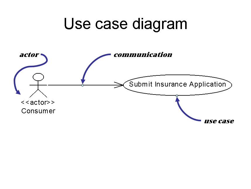
Figure 1: Use case diagram
A use case is a system action performed on some object by someone or something (the actor) and includes communication between the actor and the use case, as shown in Figure 1. The use case implements one of the fundamental concepts of OO design: namely, that a message is sent to an object and then a method is invoked to act upon receipt of the message.
A use case diagram may incorporate many actors and many use cases, each uniquely drawn as illustrated above.
The literature describing the use case states that a full text-based narrative must accompany the use case diagram for each use case. For more information about use case diagrams, refer to the Suggested Reading section at the end of this article.
Class Diagrams
The class diagram, as shown in Figure 2, is the heart and soul of UML. When you reverse engineer existing Java or C++ code, most tools generate a class diagram; the syntax of class diagrams can be refined to a sufficient level to support code generation.
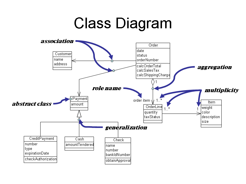
Figure 2: Class diagram
The class diagram depicts objects and the relationships that exist between objects. It's a modification of the old data modeling entity relational diagram (ERD) and is the only diagram backed by mathematics and science. The other diagrams in the UML are useful, but they are not mathematically sound or provable.
The class is defined as a rectangle containing three sections. The first and top-most section is the class name, the second section contains the attributes of the class, and the third section contains the class methods. Most methodologies model the classes from which objects are derived.
Some methodologies permit the extension of the class diagram to an object diagram (Figure 3), illustrating the relationship of instantiated objects. The object diagram is a good way to test the viability of your class diagrams. It should answer the question "Does my class diagram accurately represent my business objects?"
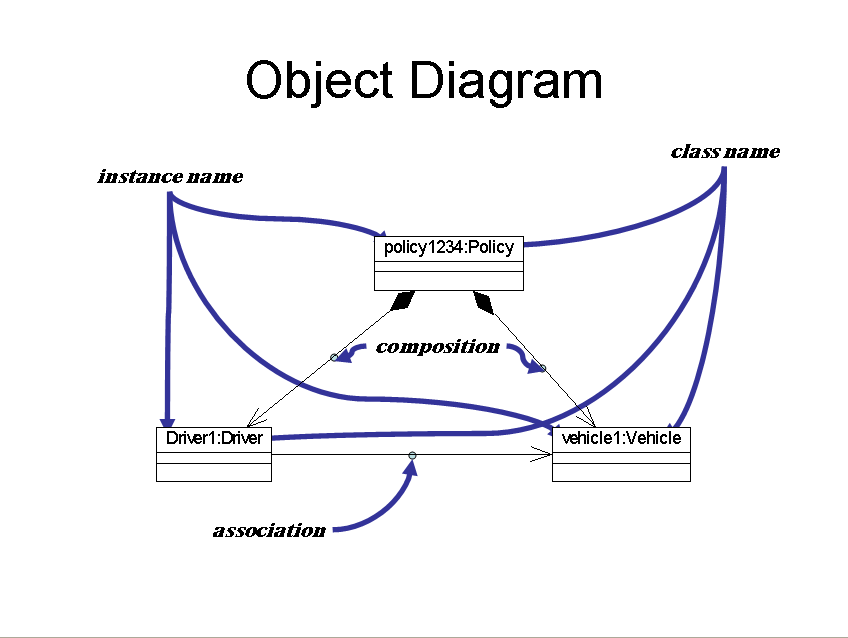
Figure 3: Object diagram
There are three basic relations in a class diagram:
- Association--In the class diagram (Figure 2), there is an association between Customer and Order.
- Aggregation--An aggregation indicates that objects of the class at the end of the line (identified by a hollow diamond) contain a collection of objects instantiated from the class at the opposite end of the line.
- Generalization--Generalization illustrates inheritance. In the example, CreditPayment, Cash, and Check inherit from the abstract class Payment. Note that Payment cannot be instantiated because it is an abstract class.
Additional relations are defined in the UML:
- Dependency--This is functionally equivalent to an association, but it's drawn with a dotted line instead of a solid line. It is designed to illustrate a dependency between objects.
- Composition--This is functionally equivalent to aggregation, but it's used to indicate that the object at the end of the line with a solid (instead of hollow) diamond is composed of objects instantiated from the class at the other end of the line.
- Realization--This is functionally equivalent to generalization, but it's drawn with a dotted line instead of a solid line. This is a subtle variation of the generalization.
When drawing class diagrams, be extremely careful to focus on the problem at hand and not on the details of the UML syntax. When you're looking at relationship types, roles, and multiplicity, numerous subtleties can cause disagreement and consume unnecessary time without contributing substantially to the design process.
Remember, the purpose of the class diagram is to identify business objects, their attributes, and methods of the objects. Doug Rosenberg of ICONIX advocates creating what he calls a "domain model" when beginning your project. Start by listing all of the major business objects in your enterprise. Use the class diagram with nothing in the class box but the class name. Model the relationships between these objects.
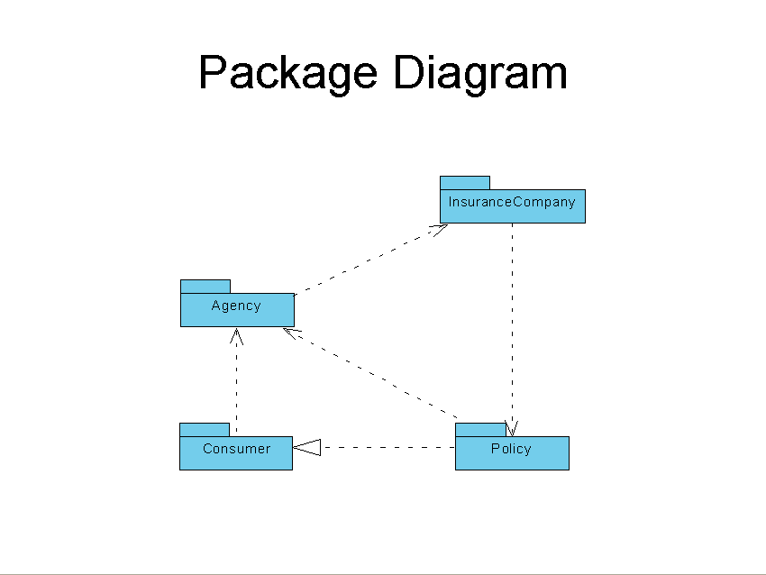
Most tools also support package diagrams (another variant of the class diagram, shown in Figure 4), which are extremely useful for modeling your enterprise and the relationship between major components. A package contains classes.
Figure 4: Package Diagram
Thus far, we have discussed static diagrams that are designed to model your enterprise or a large component of your enterprise. Doug Rosenberg of ICONIX advocates creating lists of candidate objects within your enterprise, then modeling their relationships using a class diagram consisting exclusively of class names and simple relationships. He calls this process "domain modeling."
The remainder of the diagrams comprising UML are diagrams designed to analyze the flow, control, and activities of your system.
Sequence Diagrams
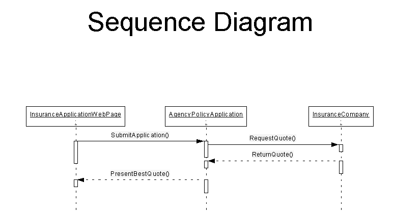
A sequence diagram illustrates the flow of messages through an OO system. In the example in Figure 5, a user enters an application for insurance on a Web page (the Web page is an object). A message is sent to the Agency system, which captures and stores the application and then requests a quotation from one or more insurance companies. The quotes are returned to the agency, which selects the best quote and returns the quote to the customer.
Collaboration Diagram
The collaboration diagram shown in Figure 6 is a variation of the sequence diagram. It is designed to show the collaboration between systems and components of a system on the same system or on a different computer system. The entity that is collaborating prefixes the name of the class involved in the system and is separated from the class name by a colon.
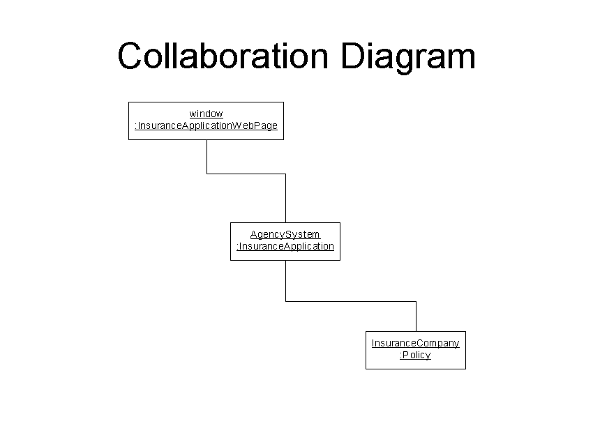
Figure 6: Collaboration Diagram
State Chart Diagram
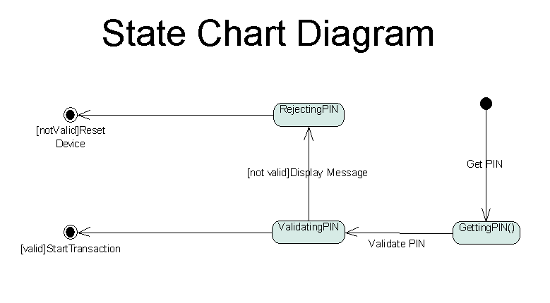
When your systems involve the changing of the state of one or more objects, the state chart diagram (Figure 7) can provide clarification of the process of setting and testing state as well as document the various outcomes when a device or object takes on each possible state.
This diagram evolved from software that controls machines, and the literature about it generally uses examples from mechanical device control to illustrate its use. However, this diagram can be used in business applications. Consider the example of an insurance policy: It may start out as an application and then change in state to an issued policy. Later it could expire, be renewed, be cancelled for non-payment, or be reinstated. Another example might be the states of an order as it moves through an order-processing system.
Component and Deployment Diagrams
A component is a software component consisting of one or more classes. A component diagram illustrates the physical deployment of software objects in a system and the flow of control between major software components. A deployment diagram is the physical deployment of an object on computer systems. Often, both diagrams are combined for representation purposes, as illustrated in Figure 8.
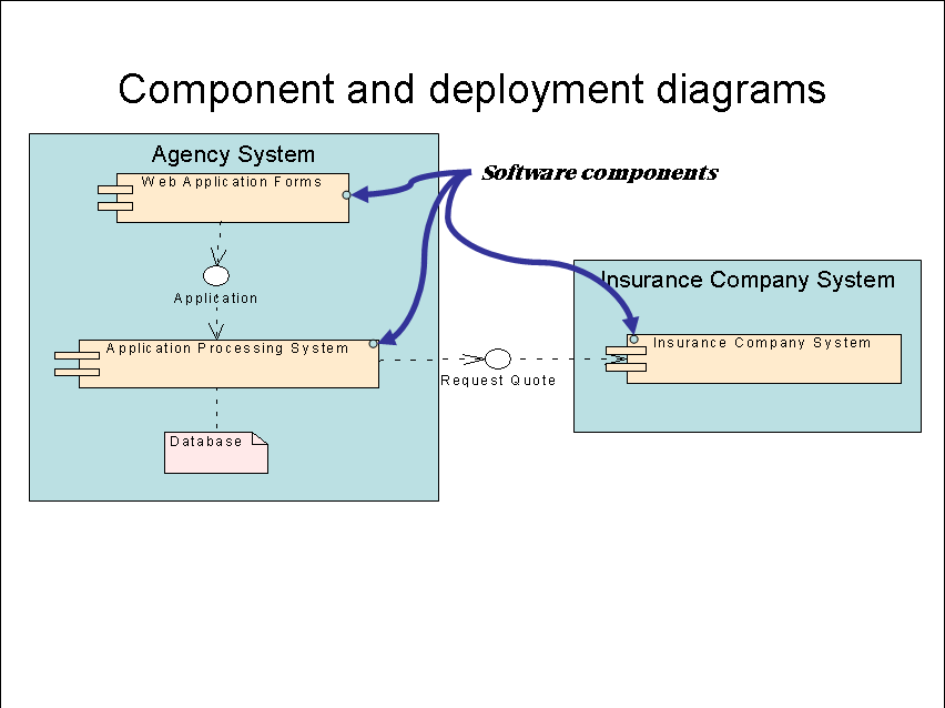
Figure 8: Component and deployment diagrams
Summing It Up
Although this article introduces some rudimentary concepts of UML as an OO design tool, it barely scratches the surface. Please review the Suggested Reading section at the end of this article for more information.
Another very inexpensive way to explore UML is via a product called Metamill, which retails at about $85 per user (much less when purchased in quantities of 10 or more).
Well-known tools such as those sold by Rational or Togethersoft retail for approximately $3,000 per user.
Last but not least, I strongly recommend TogetherSoft's "Practical UML: A Hands-On Introduction for Developers" tutorial.
Bob Cancilla is the author the popular new book from IBM Press, IBM eServer iSeries: Built for e-business. He also wrote Getting Down to e-business with AS/400, available from MC Press. Visit Bob's IGNITe/400 Web site.
Suggested Reading
The Unified Modeling Language User Guide, Grady Booch, James Rumbaugh, Ivar Jacobson, Addison-Wesley 1999, ISBN 0201571684
The Unified Modeling Language Reference Manual, James Rumbaugh, Ivar Jacobson, Grady Booch, Addison-Wesley 1999, ISBN 020130998
Use Case Driven Object Modeling with UML: A Practical Approach, Doug Rosenberg with Kendall Scott, Addison-Wesley 1999, ISBN 0201432897
Applying Use Case Driven Object Modeling with UML: An Annotated e-Commerce Example, Doug Rosenberg, Kendall Scott, Addison-Wesley 1999, ISBN 0201730391
Applying UML and Patterns, Craig Larman, Prentice Hall PTR 2002, ISBN 0130925691


LATEST COMMENTS
MC Press Online